Build and Test a Homemade Laminate
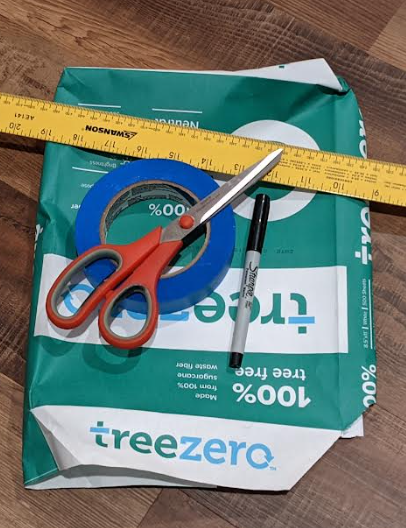
This example workflow is a simple demonstration of the provenance and geometric tracking capabilities of the MPPW, but in a deliberately simplified desktop example. In place of data from robotic systems and advanced manufacturing devices, here the design-of-experiments includes only paper, tape, scissors, a marker, and a ruler.
The goal is to create additively-manufactured specimens for a real mechanical test starting from specifications on how to "laminate" a build plate with masking tape. The process in this case is placing the tape on the paper, the preparation is detaching the laminate and cutting specimens, and the mechanical test is an qualitative measurement of strength levels required to break the specimens. By using the material process warehouse, these tests can result in a data-science-ready dataset for researchers to use in improving our tape-based materials and processes.
Design of Experiments
The first thing to do is to determine what tests to run, how many specimens to create, and so on. While there's no strict technical reason to predefine the full structure of our experiments in advance, it's good practice and good science to define the experimental process. In addition, by using the MPPW and standard operation types, it is easy to see what kinds of data we need to collect at each step and if there's something missing that could cause problems later.
For these experiments, we'll test two different cases:
- 2 layers of tape, alternating 45 degree pattern
//\\- 4 layers of tape, alternating 45 degree pattern
//\\//\\
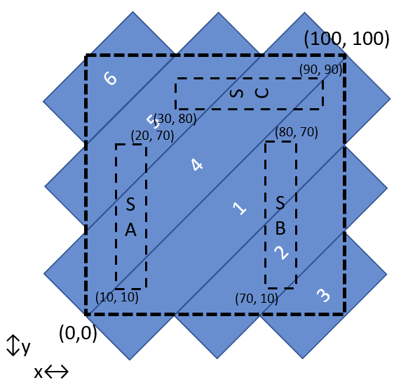
The layered laminate can be manufactured as a rough square and then rectangular specimens cut from the square. For each of the cases there will be three samples for robust statistics. The sample locations will also be tracked to better understand if the location of internal lamination boundaries have an impact on strength:
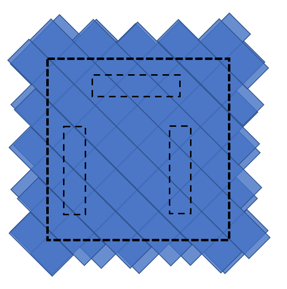
One of the specimens is aligned horizontally as a control, to allow comparing against the equivalent vertical specimen in both cases.
Precise lamination specification (GCode)
To fully define the additive lamination process, it is also necessary to generate the equivalent of GCode instructions for a person. The tape used here is 24mm wide, so creates 45° stripes of width ~33mm allowing for a 100mm x 100mm square with six pieces of tape per layer:
The human GCode can then be written as:
Place a piece of tape with top edge from (0,0) to (100, 100) (mm).
Place a piece of tape with top edge from (33,0) to (100,66) (mm).
Place a piece of tape with top edge from (66,0) to (100,33) (mm).
Place a piece of tape with top edge from (0,33) to (66,100) (mm).
Place a piece of tape with top edge from (0,66) to (33,100) (mm).
Place a piece of tape with bottom edge from (0,66) to (33,100) (mm).
(Rotate paper 45° CCW and repeat)
(for 4 layers repeat 2x more times)
Precise tensile test specification
There is no known standard for human mechanical testing of laminates, so it is necessary to create one. To match other, more standard tests by analogy it is possible to define a force-displacement graph with qualitative ranges. Here force runs from zero to 10 and two displacements:
- No force - 0, Hard as possible to pull - 10 pulling on either side of a tensile specimen
- No displacement - 0, and complete displacement - 1 (i.e. broken)
There's no possibility of creating any kind of modulus from a single tensile sample since there's no slope, but with enough data points a probability graph of breakages could be created that could be mined for interesting or even paradigm-shifting correlations.
MPPW Digital DOE
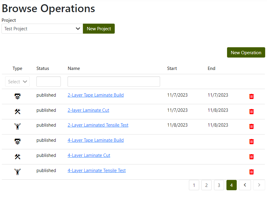
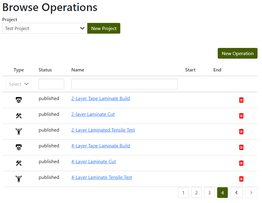
With additive process and test information well-defined, it is now possible to create a digital DOE in the MPPW. To begin, a project must be selected where the data will reside. Here the project is "Test Project", where there are already several existing operations being tracked:
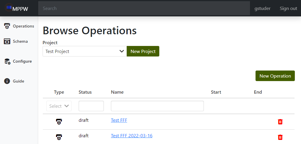
In the MPPW vocabulary, processes consist of a number of operations (which themselves consist of a number of internal steps). Generally a processed specimen will have multiple operations applied to it - in this example, the laminate is first created in a build operation (and detached from build plate), then cut into specimens (in a scissor-cut operation), and finally tested (in a tensile-test operation). Each operation has attached artifacts at named locations (either physical or digital) - in this example, the build operation has a roll of tape as a batch input and gcode as a digital file input and a laminate as a part output.
Artifacts can be created for an operation or linked from another operation - when linked, they create a provenance linking other related artifacts of that operation and operation ancestors. In the case of mechanical testing, specimen provenance is of particular interest, starting from a build, and that is what is first defined.
Build operations
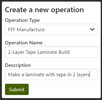
To represent the human lamination process, a new build operation is first created in the MPPW with the "New Operation" button. To avoid the complexity of defining a new operation type, the "FFF Manufacture" (Fused filament fabrication) type is used - arguably the tape could be filament and is fused by taping:
NOTE that to create (or modify) operations a user must have "Modify Provenance" permissions for a project.
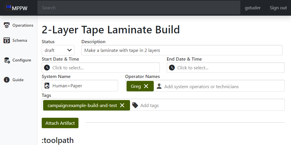
All operations have a set of basic information around the people executing the operation, the device it is executed on, and when it occurs. Any information known ahead of time can be entered along with any additional tags (such as a campaign name for organizing sets of operations):
In addition to the basic operation metadata, artifact data and to-be-collected-data known ahead of time can also be added to an operation. This skeleton data provides a structure and simplifies data entry when hectic real-world activity is occurring.
The GCode toolpath was defined above (and is saved as a text file), so using the "Attach Artifact" button it can be attached to the operation:
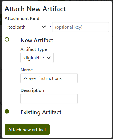
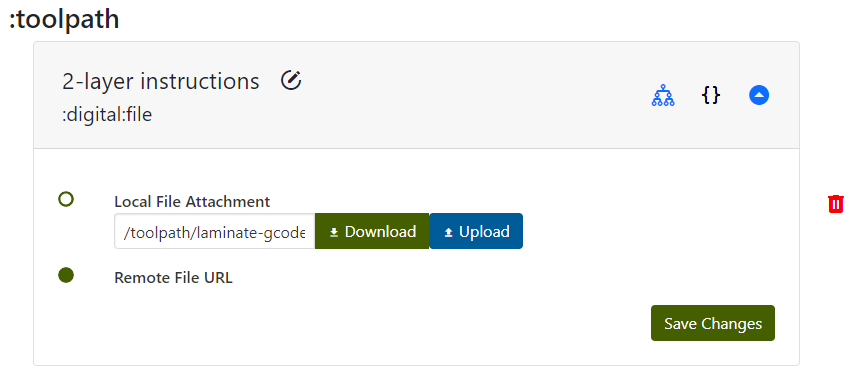
NOTE that the artifact must be added first and then the file uploaded to the artifact. It is necessary to "Save Changes" for the upload to proceed.
The input materials are also known (blue painter's tape), and so can be specified (also using "Attach Artifact"):
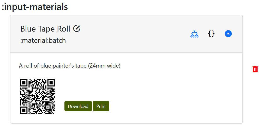
NOTE that batch materials are specified only by name and description at this time.
With the 1.0.0 version release, material artifacts are associated with a unique Quick Response (QR) code. QR code is an efficient way to link physical objects with their digital representation or further information. Users can download and print this QR code immediately after an artifact is manufactured, ensuring that each item is labeled accurately from the outset. Once labeled, these QR codes will enable users to trace and monitor the artifact throughout its lifecycle by scanning it.
Placeholder parts and measurements
Though the experimental campaign has not yet started, as mentioned above it is possible (in many cases) to define beforehand the expected input and output artifacts for operations. Here, though it is not yet built, a material:part artifact (representing the 2-layer laminate) can be attached as the specified output of the draft build operation. The idea is similar to written DOEs where a part and specimen naming scheme is decided beforehand - in the MPPW, parts can be named and created beforehand (and generally have UUIDs, so names can be assigned for clarity in human use).
Creating a placeholder part later operations in the digital DOE (such as cutting and testing) to refer to earlier operations, ensuring a valid digital specimen provenance is in place before any real-world work begins. Additionally, it allows for placeholder measurements to be attached, representing data that should be collected when the operation is executed.
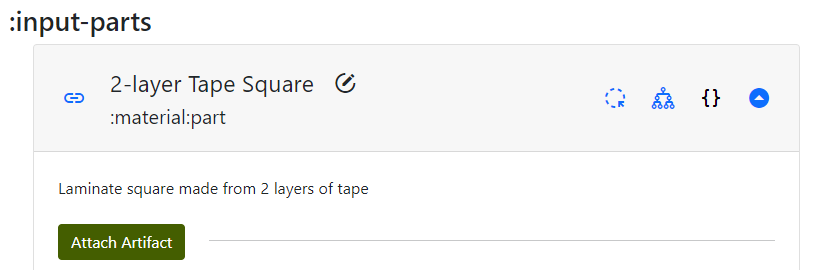
Next the placeholder "2-layer Tape Square" output part is created (again using "Attach Artifact"):
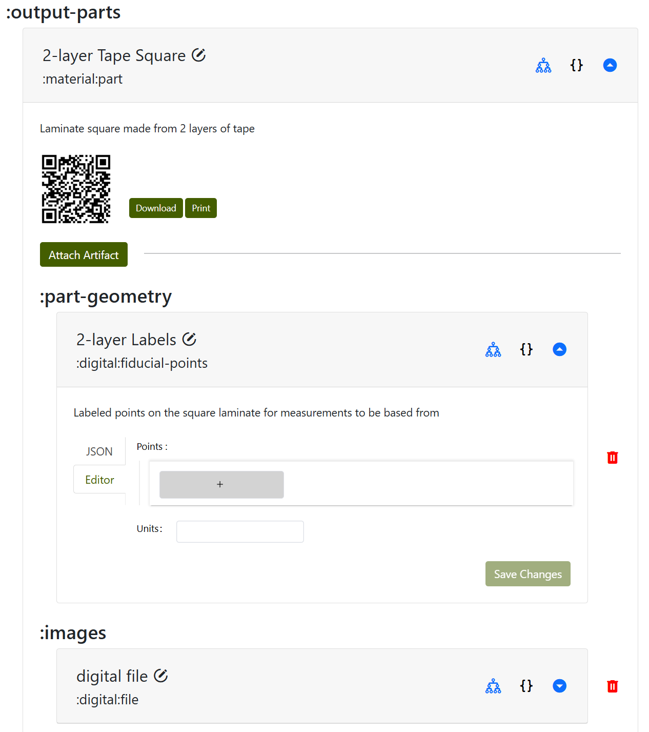
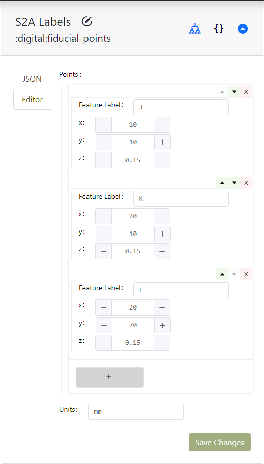
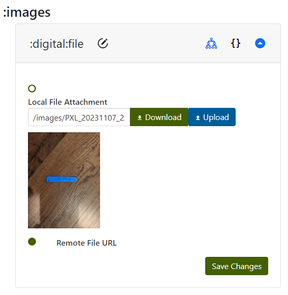
Placeholder measurements also created that should occur for every new physical output part of every operation - fiducial points and images. Fiducial points are physical labels that are linked to digital coordinates - often written on the part with colored markers - that allow for further measurements linked to existing data to take place. The term is sometimes unfamiliar but the basic idea is natural - writing "bottom" on a board to indicate the side that wasn't sanded and should be installed facing downward. Fiducial markings allow parts to be oriented relative to a design even if handled and moved. The main difference with digital tracking is that these physical markings also have to be assigned digital coordinates, but this will be revisited later.
Taking digital images of all new or cut parts is cheap, makes the data nicer to read for people, and, if fiducial points are visible, provides a valuable backup for reconstruction of measurements.
No data can yet be added to either the fiducial points or the image, the empty dialogs are a reminder for data collection and to create a measurement provenance.
Attachments
Ideally all operations would have named attachments for all relevant data, but in certain cases there may be additional information that is hard to model or not currently modeled. To make sure any kind of data can be added, every operation contains a special kind of file-bucket artifact called "Attachments" (similar to a directory of unlimited size) which allows uploading (and downloading) any kind of file:
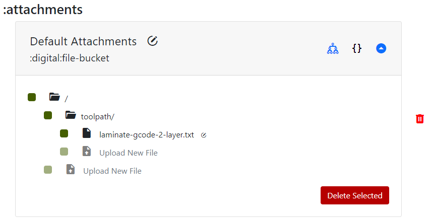
NOTE that it may be necessary to reload the operation to see any files uploaded as other artifacts.
The human GCode that was uploaded earlier as a :toolpath attachment also appears here - all named file artifacts uploaded (including images) are, under the covers, uploaded as standard file attachments with a link stored as metadata.
Provenance
By clicking on the "family tree" icon of any artifact:
![]()
it is possible to view the related ancestor artifacts and operations of a particular material part or a digital measurement. This provenance allows human and machine exploration of the processes that may have influenced a particular measurement, which is the raw data for scientific and data-scientific exploration of these relationships. Though there is only a build operation so far, it is still possible to view the state of the provenance of the placeholder output artifact:
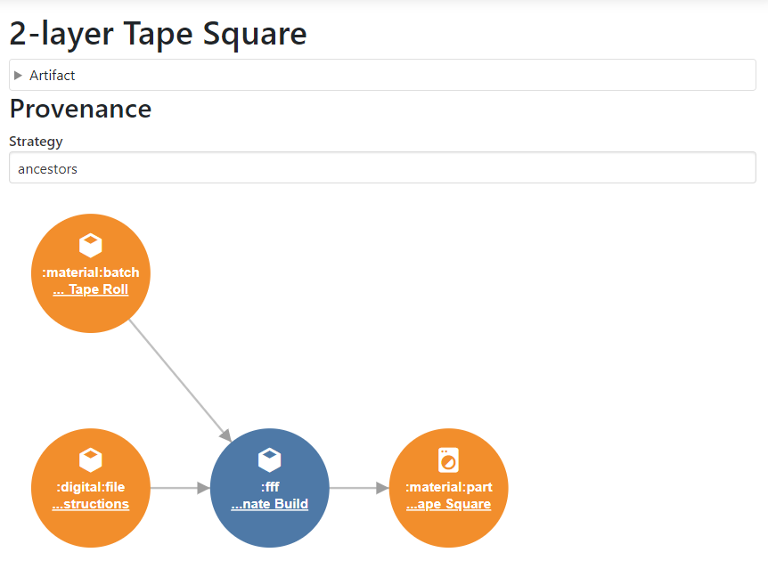
As can be seen, the input batch (roll of tape) and gcode (instructions above) will be used in an operation to produce the placeholder output part, represented by the graph.
... and so concludes the pre-definition of the 2-layer laminate build operation. The 4-layer laminate can be defined in a similar way, left as an exercise to the reader.
Cut operations
After the laminate is built, the next step is to cut out the samples - a scissors-cut operation would be ideal for this, but to (again) avoid creating custom operation types the "Generic Machining Operation" can be used:
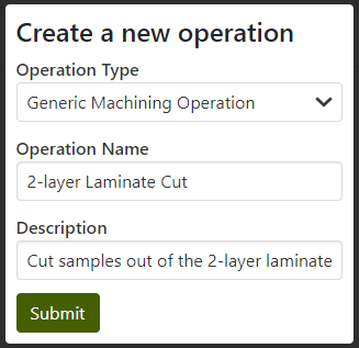
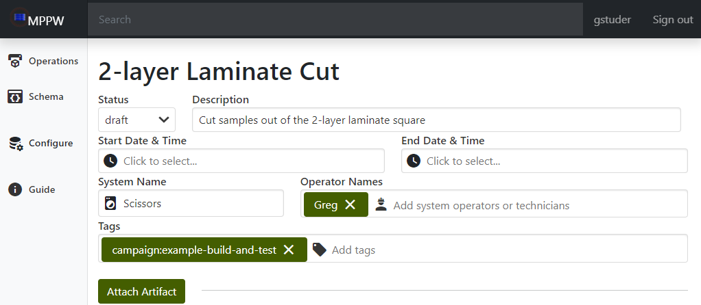
A "Generic Machining Operation" generally captures the idea of taking parts and changing them or cutting them into pieces. Here, we're taking the 2-layer laminate square and cutting three samples from it. First, the standard operation metadata is filled with basic who/what information:
Linked input part (artifact)
Next is the step where a provenance is truly established. The 2-layer cut operation will reference an existing part - the 2-layer laminate square - as the input part. The workflow is the same, "Attach Artifact", but instead of creating a new artifact the square is referenced from the build operation:
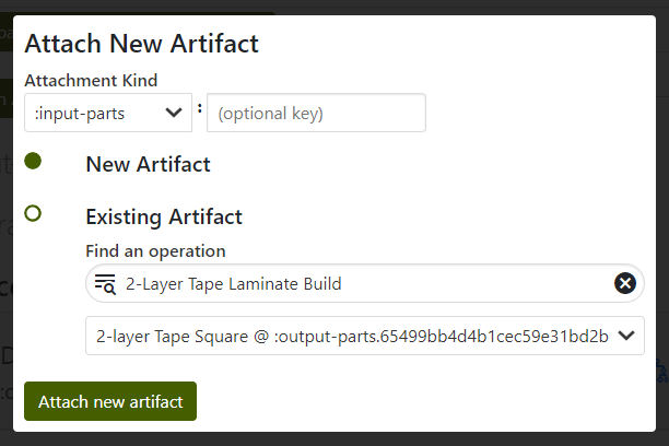
Note that the cut input part has a blue link next to the name - this indicates the artifact was first initialized elsewhere (in the build operation).
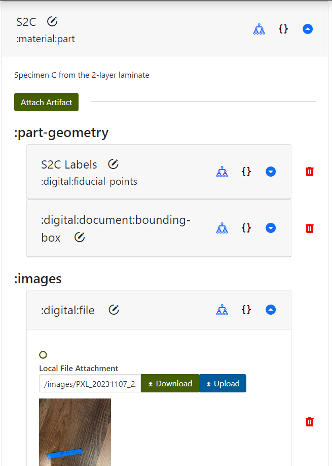
Placeholder specimen output parts
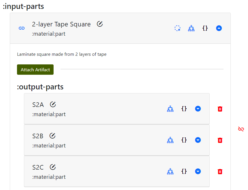
Once there is an input part, "machined" output parts (specimens cut with a scissors) can be defined. From the DOE diagram, these specimens are called SA, SB, SC. Whoops - there's a bit of confusion, because there aren't different specimen names for the 2-layer and 4-layer tests. That doesn't really matter in the MPPW - the specimens would have UUIDs and the names are just helpful, but to avoid confusion the specimens can be named S2A, S2B, and S2C instead:
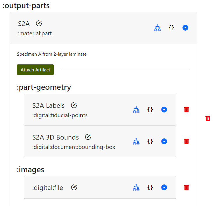
Importantly, as will be shown later, the specimens are cut from the square using measurements from the fiducial points marked after build. The laminate squares aren't going to be left on the build paper, so we need markings to know where to cut. Once the specimens are cut themselves, they'll also need new fiducial points so we can align them consistently during our manual tensile tests. Generally, every operation that creates new parts should also define new fiducial points and an image for tracking.
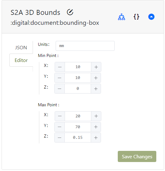
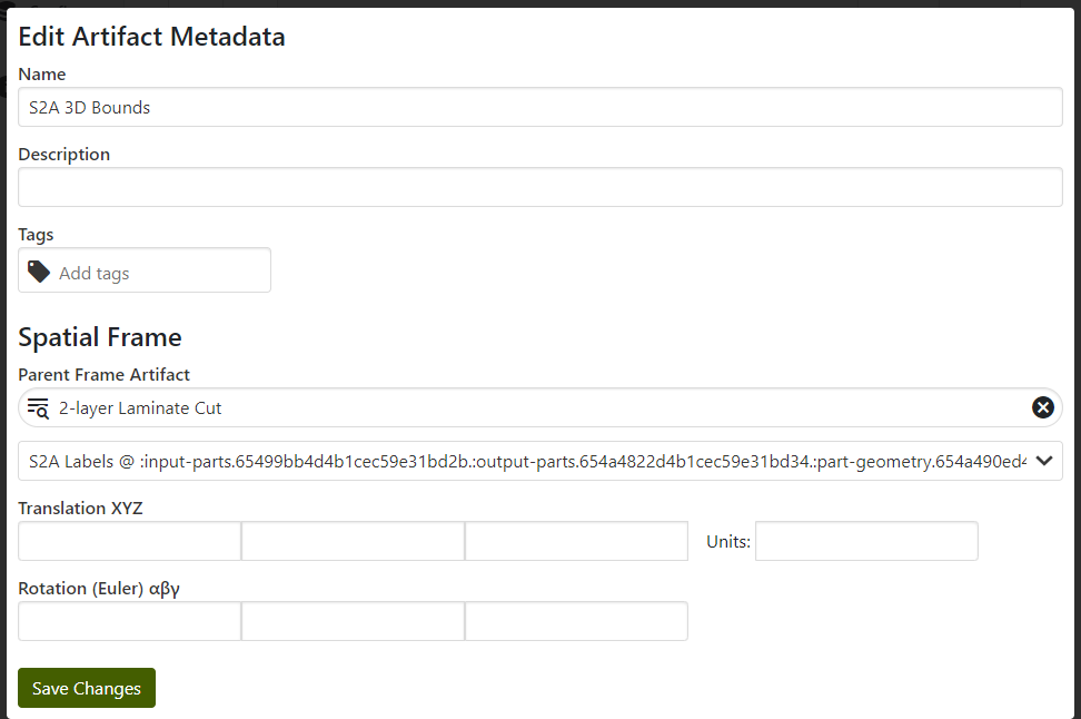
As a new addition, the specimen can also have a 3D bounding box attached. Adding a bounding box allows the MPPW to later query data from the build operation in the region of the specimen - for example, to determine if there were flaws in the taping in that area that might impact results. Bounding boxes are also logically measured from a set of fiducial points, sometimes with a tolerance. Restating this, to avoid confusion:
- Fiducial points - reference points for measurement in the real world, linked to coordinates in a design. Used to perform further measurements in the real world in reference to a design.
- Bounding boxes - volumetric measurement of the shape of a part, the simplest possible "mesh" that represents a part shape. When linked to a design or fiducial points, can be used to query only relevant 3D regions from data sets.
In the case of these laminated specimens the thickness of a bounding box will probably be very small - not zero, though. Most of the interesting information is probably in correlating tape interfaces in the X/Y plane to mechanical results.
Again, note how there is no data yet in any of these measurements - they are just being pre-populated to create the DOE and provenance. These can be added to all output specimen parts.
In more specialized cut operations a machine toolpath can also be specified - here we're ignoring that detail. As in the build operation, any other kind of file can also be added to the "Attachments" section of the cut operation. For now, just specifying input and output parts is the only data we track.
NOTE that there is nothing preventing a "cut" operation from being a primary source of data collection - here the implicit DOE assumption is that the actual motions of the scissors won't impact the mechanical strength much. Collecting and registering that data in all cut operations, however, would let data science scripts actually validate those assumptions.
Provenance
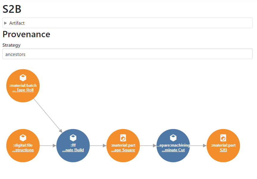
By choosing to visualize the provenance of an output specimen, it is possible to see how the provenance has been extended after creating the cut operation:
Tensile Test Operation
Finally it is time to define the manual tensile test operation of the DOE. A standard "Tensile Test Operation" is used filled with the standard metadata as above:
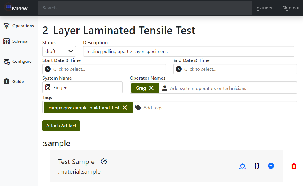
Note that a test operation has a :sample artifact pre-populated - this artifact can be renamed. A sample is just a logical container for multiple specimens in a test.
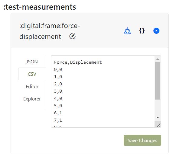
Like the cut operation, the first task is to link the cut specimens as specimens in the sample artifact. Each specimen will be tensile tested, requiring the collection of (named) specimen measurements based on the test being performed, force/displacement data (as described in the DOE), and, once tested, the broken sample is recorded with an image:
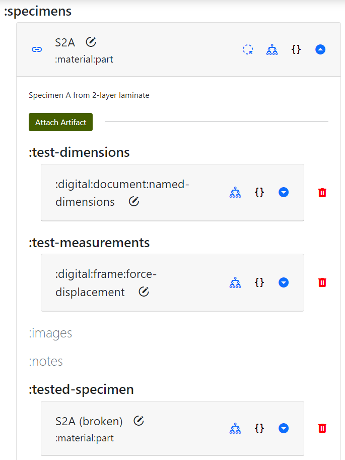
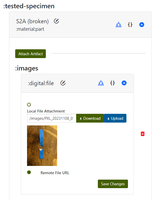
The takeaway here is that even the "broken" specimen is tracked as an output of the test. If further analysis were to be done, for example a fracture analysis, the broken pieces would need to be marked with new fiducial points. In this DOE there are no further tests, so just an image of the broken pieces allows us to get a human sense of what the break looked like.
Provenance
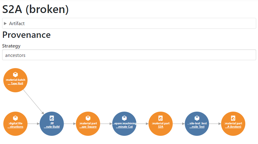
Visualizing the provenance of the broken specimen, it can be seen that the chain reaches all the way back to the build operation - the digital DOE we entered is complete. The operations can be marked as "published" and the tests are now ready to run. If this was a real test, the manufacturing and experiments might be run by a completely different team, making it important that all the information required to execute the processes is in the MPPW.
Building the Laminate
Putting on an "Operator" or "Technician" hat, the MPPW build operation is ready to be executed and contains instructions to do so. The MPPW digital DOE is now going to be filled in by activities in a desktop manufacturing lab. First blue tape of the appropriate type is collected, the start time is entered, and operator notes are added to the build operation indicating any kind of information not captured elsewhere:
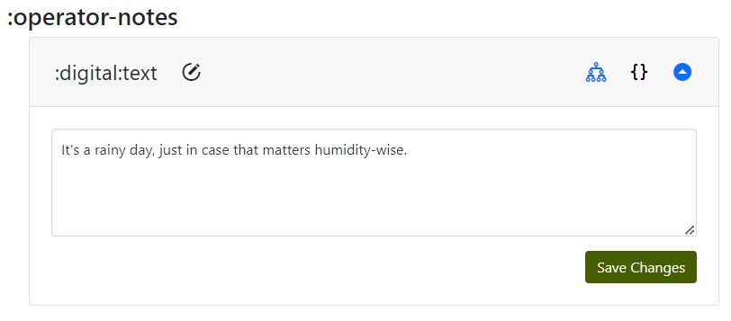
These notes can be added to during the build operation, generally if something unexpected happens that should be noted for posterity.
Process Data
Process data is the complement of "Attachments" artifacts in the MPPW - every operation has a database to which large time series from sensors can be written. Generally this process is semi-automated - the instruments in the lab are pointed at the MPPW URL to write data as it is captured. In our example case, we don't have automated instruments recording second-by-second progress. We can emulate something similar, however, by taking pictures every layer:
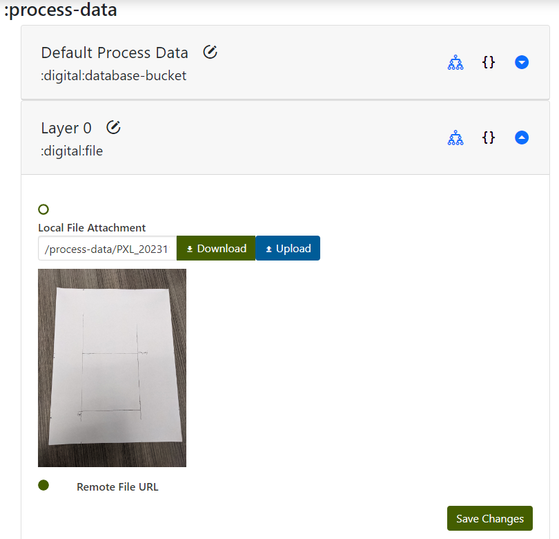
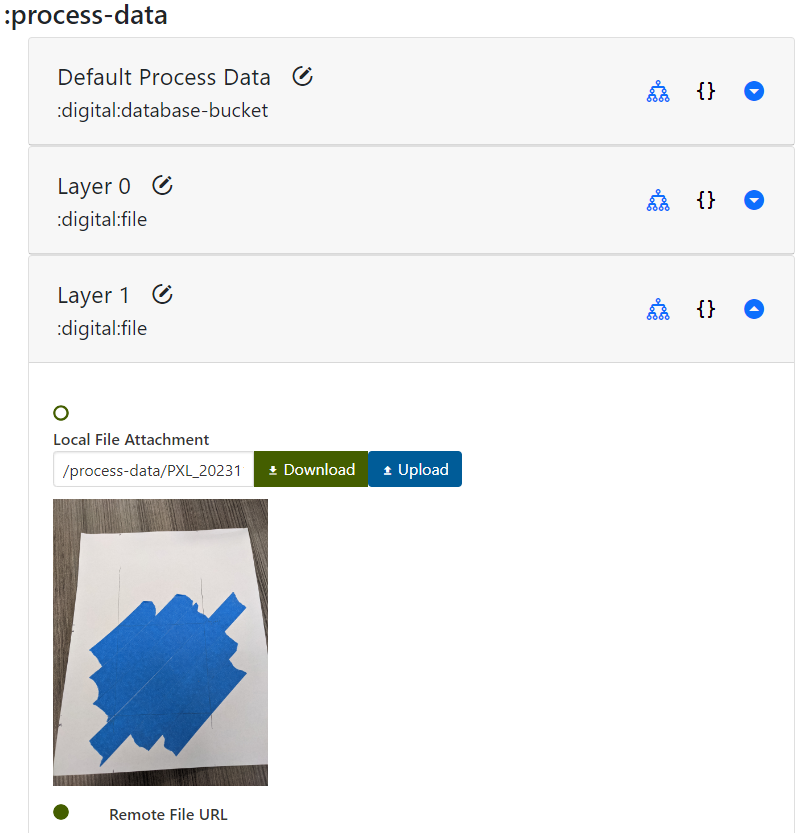
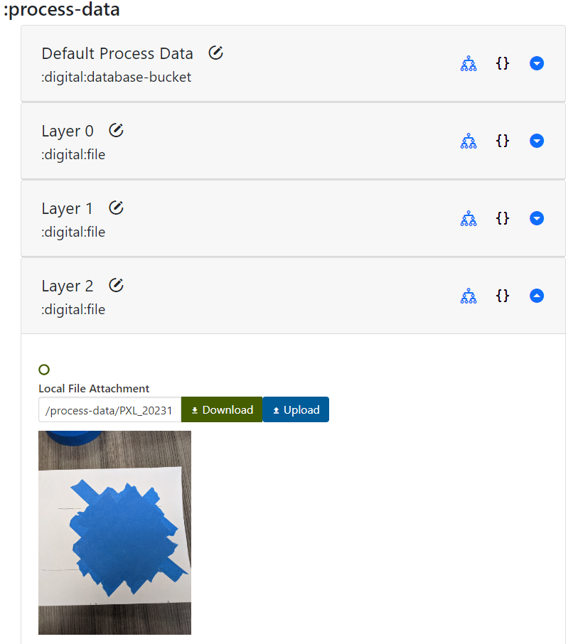
This provides a rough "time series" that, if images were registered in space, could provide real data on defects in our laminate construction that could be correlated with tensile test results.
Fiducial Points
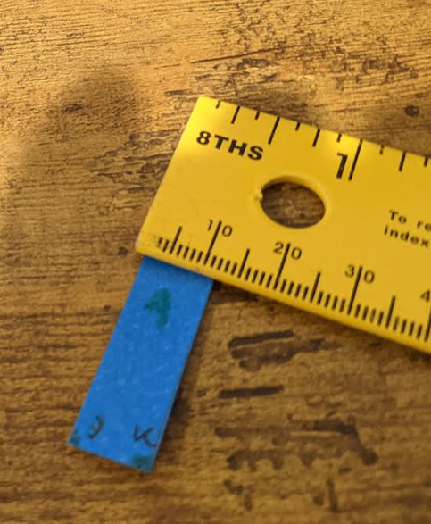
Once our laminate has been manufactured it can be removed from the build plate. Before that happens though, it needs to be marked with some fiducial points so that further specimens can be cut and measured. Here we've marked three points at the corners of the original square that was marked:
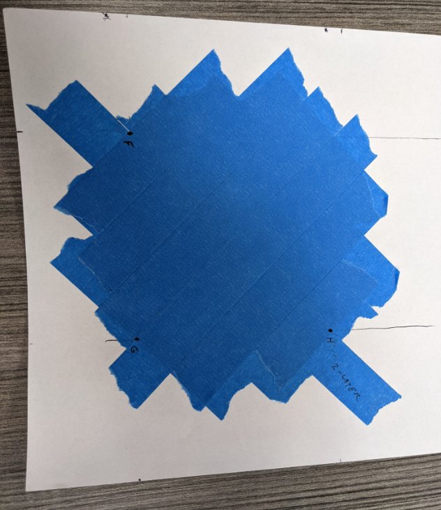
An image is taken of these fiducial points in place, for human use and as a backup, and the fiducial points themselves are entered with the corresponding coordinates (assuming tape and paper thickness is 0.05mm):
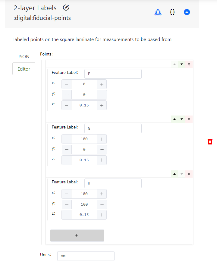
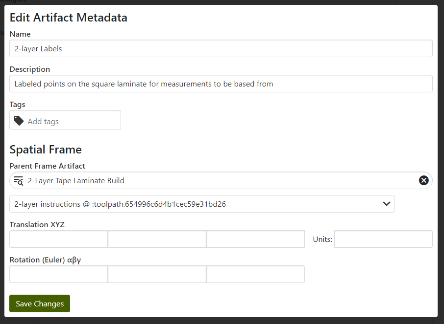
Spatial measurements of all kinds generally need to be related back to some kind of reference coordinate system. In the case of these fiducial points, the coordinate system ultimately came from the GCode - the design. For example, the point "F" at (0, 0) corresponds to the (0, 0) coordinate in the GCode instructions. In the MPPW, this link must be made explicitly to say what "reference frame" the coordinates are in relation to:
It's also possible to transform the reference frame of the fiducial points - this is sometimes done for a vertical wall, for instance, if it's more convenient to refer to parts cut out of a wall's XY plane vs the build volume's XZ/YZ planes. When possible, however, it's usually simplest to stay in an earlier reference frame unless there's a good reason to change.
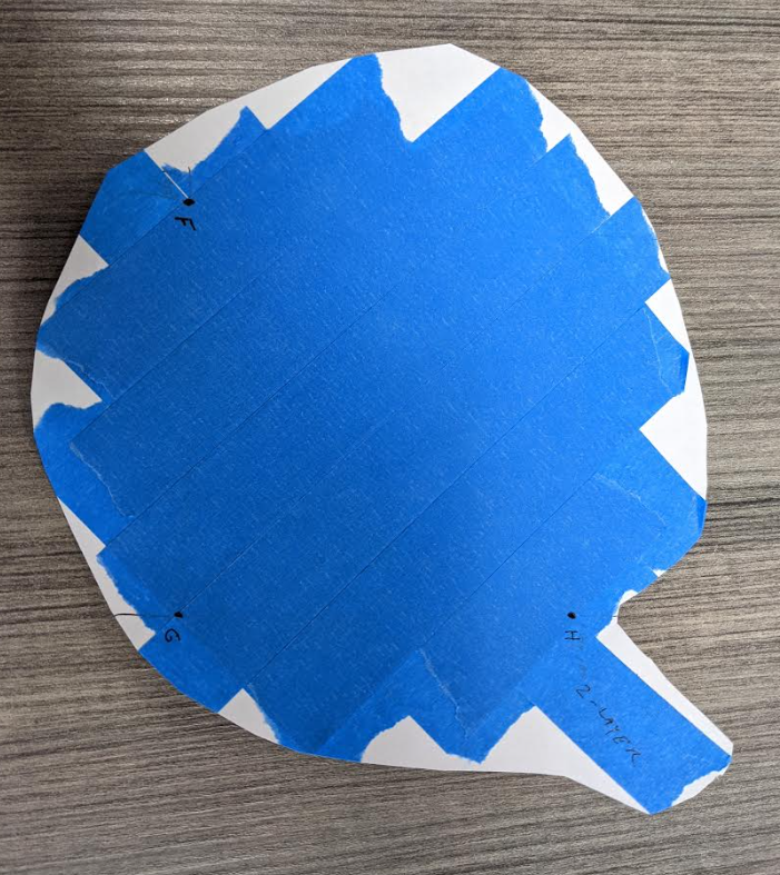
As can be seen when the laminate is cut off the plate, the points have to be marked beforehand because otherwise there's no way to re-find the original locations relative to the build plate / gcode:
The last action to take place is to mark the time completed and save the operation metadata.
Cutting the Specimens
Secondly, the specimens must be cut from the laminate square, helpfully marked with fiducial points to guide the cut. As usual, the start time is entered and operator notes can be added to the cut operation.
Next, the measurement for the cuts proceeds - before the specimens are loose, however, it is important to mark fiducial points. On a bigger set of specimens an easily-identified pattern could be painted, or other strategies:
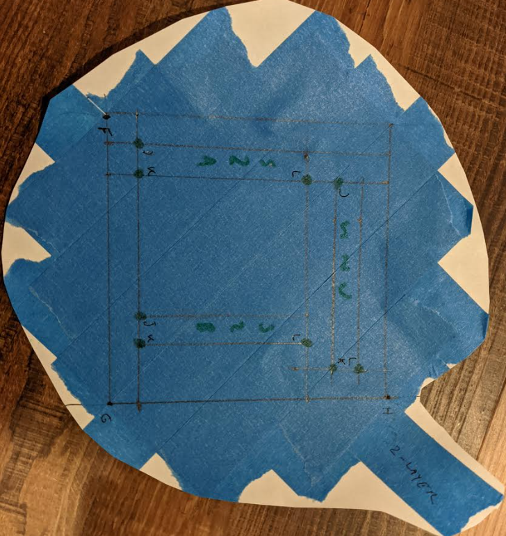
Note that each specimen has three clearly-identified corners - these are marked based on larger square laminate fiducial points F, G, and H. This is entered in the data warehouse in the same way, the fiducial points are named (names can be reused if not confusing), coordinates assigned, and then linked to the parent fiducial point spatial reference frame:
As mentioned earlier, to allow searching the build process data by 3D region it is necessary to add that 3D geometry to our specimen. As a bounding box was pre-populated, coordinates can now be filled and the coordinate system linked to the specimen fiducial points reference frame:
Finally, we take an image of every specimen for later reference:
... and the result is a fully tracked set of cut-specimen data:
Since all artifacts were created beforehand, it was arguably simple to remember to just fill-in-the-blanks with the fiducials, bounding boxes, and image information. Often the machining operations are least-tracked - collecting 3D print data and test data is obvious, but the machining information is really what links the two.
Finally the end time is marked and the cut operation is complete.
Testing the Specimens
As the final operation, the tracked specimens are ready to be tested. Mechanical testing often consists of dimensioning and then capturing force/displacement data. Generally in a real test the dimensioning operation would be handled separately, as mentioned above, but here the operations are more streamlined. Testing is probably the most straightforward data entry in the MPPW once the earlier provenance is carefully managed.
Dimensioning
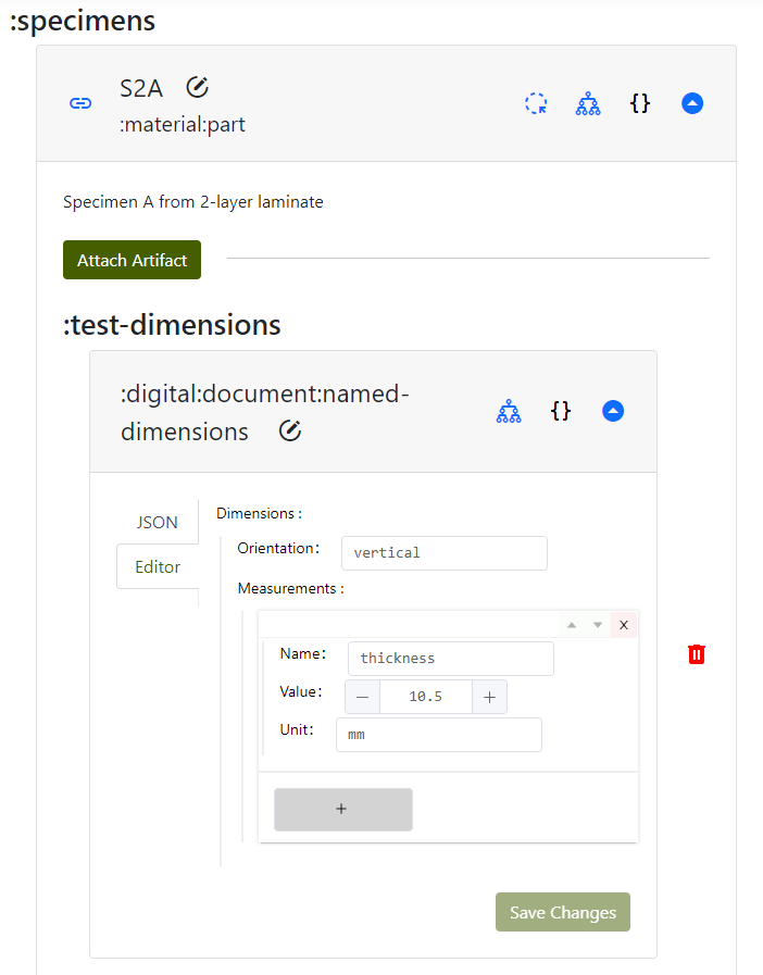
Most mechanical tests in the MPPW use a :named-dimensions artifact - this is a set of measurements with names required by a particular standard. For these tests the orientation of a specimen is captured (relative to some test-specific geometry, in this case the laminate pattern) as well as the specimen center thickness (via ruler):
This gets entered in the MPPW like so:
Force/Displacement Testing
After all this setup, the specimens are ready for force displacement (really force breakage) testing. Hands are prepared and the specimen is placed between fingers with the "J" facing upward under the left thumb and the "L" facing upward under the right thumb. (Correct placement in the test machine is very necessary to track and is added here under operator notes.)
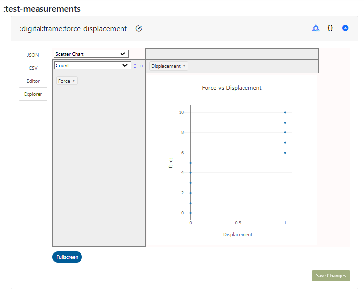
Success! The first specimen broke with strength ~6, and all data was recorded:
...including the image of the broken specimen, attached to the post-test specimen artifact:
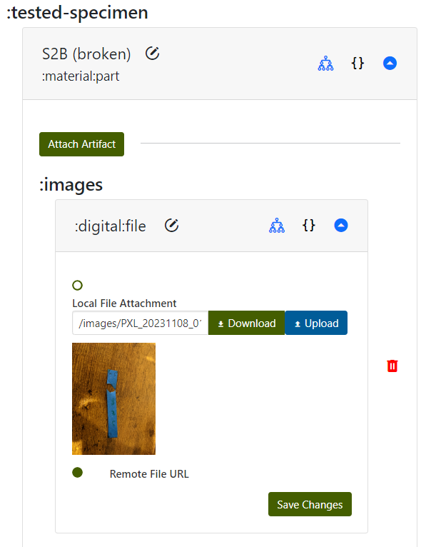
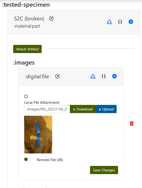
Initial results are that the specimens that broke along tape edges were noticeably easier to break (A, C) while the specimen which broke by ripping a tape layer (B) was much harder to displace. By tracking where the specimens were cut and relating this to the build taping process as part of the specimen provenance, patterns may emerge where laminated material is much weaker if it includes more tape interfaces. Without the tracking information, however, further analysis is much harder. In this example the tape boundaries are still partially visible post-test, for 3D printed thermoplastic parts the thermal history is effectively invisible once the print completes.
Once the same process is completed for the 4-layer laminate and specimens, a multi-layer tape-laminate mechanical test dataset exists in the MPPW for use by any researcher. The data can be explored, managed, and downloaded in the web interface, or, as will be discussed in the next tutorial, can be queried in interesting ways for scripted analysis and data science.